Question
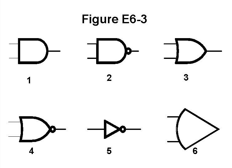
In Figure E6-3, which is the schematic symbol for a NOR gate?
Answer Options
- A) 1
- B) 2
- C) 3
- D) 4
Correct Answer: D
Explanation
Figure E6-3 displays schematic symbols for various digital logic gates. A NOR gate (NOT-OR) is a combination of a standard OR gate followed by a NOT (inverter) function. The symbol for this is derived from the basic OR gate shape, recognizable by the curved input side.
Symbol 4 is the correct schematic symbol for a NOR gate. It shows the distinctive pointed-arch shape of the OR gate but includes the small circle, or negation bubble, on its output line. This bubble indicates that the output is high (logic 1) only when none of the inputs are high (logic 1).
This topic was automatically created to facilitate community discussion about this exam question. Feel free to share study tips, memory tricks, or additional explanations!