Question
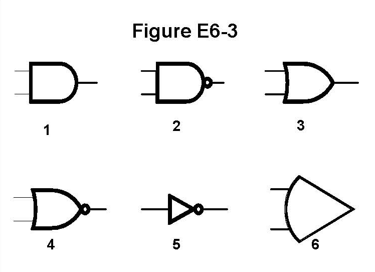
In Figure E6-3, which is the schematic symbol for the NOT operation (inversion)?
Answer Options
- A) 2
- B) 4
- C) 5
- D) 6
Correct Answer: C
Explanation
Figure E6-3 displays schematic symbols for digital logic functions. The NOT operation, or inverter, is the simplest of the gates, as it only has one input and one output, and its function is simply to reverse the input logic state (a ‘1’ becomes a ‘0’, and a ‘0’ becomes a ‘1’).
Symbol 5 is the correct schematic symbol for the NOT operation (inversion). It is represented by a small triangle followed by a circle (the negation bubble) on the output line. The bubble is the essential part of the NOT operation, indicating the reversal of the logic state.
The negation bubble is also part of other gates which include negation, like NOR and NAND.
This topic was automatically created to facilitate community discussion about this exam question. Feel free to share study tips, memory tricks, or additional explanations!