Question
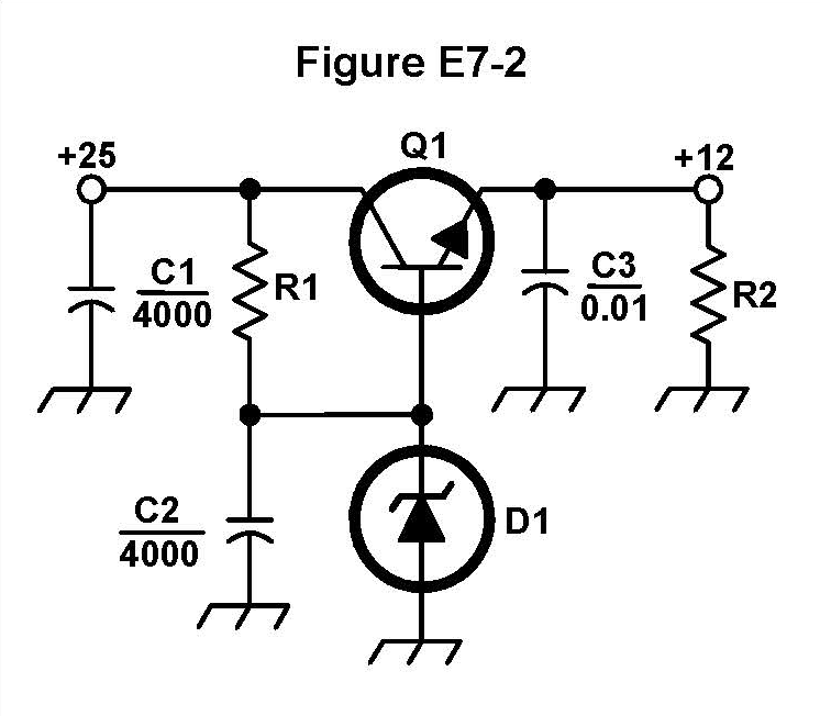
What type of circuit is shown in Figure E7-2?
Answer Options
- A) Switching voltage regulator
- B) Common emitter amplifier
- C) Linear voltage regulator
- D) Common base amplifier
Correct Answer: C
Explanation
Figure E7-2 shows a circuit containing a series pass transistor (Q_1) and a Zener diode (D_1). The Zener diode provides a stable voltage reference, and the series pass transistor drops the difference between the input voltage (+25 \text{ V}) and the regulated output voltage (+12 \text{ V}). This is the fundamental architecture of a regulated power supply.
Because the regulation is achieved by varying the conduction (resistance) of the series pass transistor Q_1, which continuously dissipates the excess voltage as heat, the circuit is defined as a Linear voltage regulator. It is specifically a shunt-series regulator, where the Zener acts as a shunt reference, and Q_1 acts as the series control element.
This topic was automatically created to facilitate community discussion about this exam question. Feel free to share study tips, memory tricks, or additional explanations!